Garrattfan's Modelrailroading Pages

LTM 51 in HO
Drive unit superstructure
- Introduction
- History of the LTM 51
- Inventory of the kit
- Instruction manual
- A preview
- Project preparations
- Boiler cradle - Main construction
- Pivots
- Boiler
- Drive units - Chassis
- Sprung frames
- Gearbox and motor
- Coupling rods
- Drive units - Superstructure
- First assembly and trial run
- Drive units - Detailing
- Boiler cradle - Detailing

In het Nederlands
 |
|
High spots evident when sanding marking ink away |
The superstructure of the drive units starts with two sheets of brass. The front and rear of the engine housing are folded upwards. The top and sides are bent from one sheet over a piece of aluminium profile which I filed to suit in a very similar way as with cab side sheets. After a lot of fiddly folding I sizzlingly soldered the bent brass to the ready running board. I did not heed my own warnings not to build up too much heat while soldering. I worked too fast and the running board warped. I managed to straighten it on the edges but a few high spots (low on the underside) where obvious when I sanded the underside after marking it out. As this is about tenths of millimeters I left as it is. |
 |
The holes for the buffers and the coupler where marked out using the buffer beam as a template |
 |
Followed by a bout of drilling |
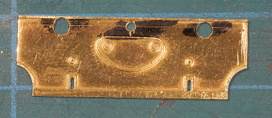 |
Despite careful work I managed to miss the correctly marked position of the right hand buffer. The hole for the coupler was later squared by scraping it out with a no 11 (HSS) blade. |
An ominous meeting. LTM 26 and NS 6200 visiting the building site. |
|
 |
Why ominous? Well, in 1939 an NS 6200 towed the LTM 51 and a string of surviving LTM B-couplers to Dotremont's scrapyard after the closure of the line Maastricht-Vaals. When I complete LTM 51 I will have built one example of all three locomotives classes in this photo. |
 |
 |
The front sheet would match up correctly with the side sheets so I filed the slightest bit away, about 0.4 mm deep. |
|
 |
I also trimmed about 0.4 mm from either side of the front sheet. As supplied the front sheet is of the same width as the running board and it is evident from some photos that the running board overhangs the side sheets. |
 |
The side sheets where carefully laid out and tack soldered. I meticulously measured the parallelism and perpendicularity of the side sheets before making the solder join permanent. |
And finally the running board was mated with the front and side sheets |
|
 |
 |
 |
The buffer beam was soldered in place and the coupler test fitted. The coupler will stay in the storage box until after painting. |
 |
The LTM buffer stocks are of a slightly different shape as the NS version I have but the overall dimensions are close enough. An attempt to turn one in the lathe miserably failed when the tool grabbed the part and completely maimed the soft brass. So the following four were stuck in the lathe chuck and filed to shape with the lathe running at a low rpm. The shallower taper was a challenge. |
 |
 |
| A little notch had to filed to clear the running board | |
A first mating of a drive unit with the boiler cradle and the frame (as good as invisible), albeit loosely fitted. It is beginning to look like the real loco. |
|
|
|


 And once the frames were ready and mated to the superstructrure I had two completed power units.
Sign my
GuestBook